A 12-inch rise in the local seasonal high-water table can reduce a conventional drainfield’s hydraulic processing capacity by up to 80%, transforming porous sand into a subterranean dam.
Central Florida’s subsurface environment presents one of the most unforgiving dynamic contexts for onsite wastewater treatment systems (OWTS) in North America. When a multi-family housing development in Kissimmee or a commercial facility in Orlando experiences chronic drain lines backing up, the root cause rarely stems from a simple mechanical blockage. More often, it is a structural failure of soil physics.
In low-lying sandy soil matrices, the delicate interaction between wastewater effluent, soil oxygenation, and hydraulic head pressure breaks down the moment groundwater encroaches on the unsaturated zone. Understanding the physics of soil absorption in these environments requires looking beyond simple pipe hydraulics to examine unsaturated flow mechanics, biological clogging dynamics, and municipal site engineering.
How Saturated Soil Halts Percolation
How High Central Florida Water Tables Cause Drainfield Saturation
High seasonal water tables reduce the vertical distance of unsaturated sand required for capillary action, trapping effluent, choking aerobic microbes, and causing severe hydraulic surficial surcharging.
Central Florida sand formations—primarily Myakka, Candler, and Immokalee fine sands—are characterized by high porosity but exceptionally low organic content. In ideal conditions, these soils process liquid effluent through gravity-driven downward percolation and lateral capillary action. However, the region’s subtropical climate introduces massive seasonal water table fluctuations driven by intense summer convective rainfall.
Structural Comparison of Conventional vs. High Water Table Systems
In a conventional septic drainfield system:
- The distribution pipe or trench sits at the top of the assembly.
- A thin, healthy biomat layer forms directly beneath the pipe.
- A minimum unsaturated treatment zone of 24 inches or deeper provides active biofiltration.
- The groundwater table remains well below the treatment zone, allowing continuous aerobic breakdown and downward drainage.
In a high water table system:
- The distribution pipe or trench sits in the same physical location.
- An unhealthy, thickened biomat layer forms beneath the trench due to oxygen deprivation.
- The critical unsaturated treatment zone shrinks dramatically, often to less than 12 inches.
- The seasonal high water table rises into the treatment zone, creating a saturated, oxygen-depleted environment.
- As a direct result, the biomat suffocates, wastewater surfaces above ground, and effluent backs up into building plumbing lines.
When the Seasonal High Water Table (SHWT) rises, the vertical separation between the bottom of the absorption trench and the saturated zone shrinks. Florida administrative codes enforced by the Florida Department of Healthrequire a strict minimum of 24 inches of unsaturated soil beneath the drainfield header and trench bottom. This separation distance is not an arbitrary regulatory boundary; it is a fundamental requirement of fluid dynamics and soil microbiology.
When groundwater encroaches within this 24-inch boundary, three distinct physics-driven failures occur simultaneously:
- Loss of Capillary Suction: In unsaturated soil, negative pore water pressure (matrik potential) actively pulls liquid away from the distribution pipe. As the soil nears 100% saturation, matrik potential drops to zero, eliminating capillary suction and relying entirely on slow, saturated hydraulic conductivity.
- Aerobic Microbial Suffocation: Bioremediation of primary-treated effluent relies on aerobic bacteria residing in the unsaturated pore spaces. When water fills these voids, dissolved oxygen levels plunge, killing aerobic microbes and halting the breakdown of suspended solids and pathogens.
- Biomat Thickening: In anaerobic conditions, specialized bacteria produce sticky extracellular polymeric substances (EPS). This forms an impermeable black slime layer known as biomat along the soil trench interface, permanently destroying natural soil percolation rates.
In high-water-table regions like Winter Park, Sanford, and Lake Mary, residential and commercial properties experiencing septic system problems frequently misdiagnose this hydraulic stalling as a simple tank issue. Pumping the septic tank provides only temporary relief because it treats the storage vessel rather than the blocked soil interface.
When the surrounding water table remains elevated, groundwater acts as a hydraulic wall, preventing effluent from leaving the tank and pushing wastewater back up into low-lying property fixtures.
Engineering Mechanics of Soil Percolation Rates and Hydraulic Loading
Drainfield design depends on balancing daily hydraulic loading rates with soil percolation rates to maintain continuous unsaturated fluid flow through sandy subsoil matrices.
Designing a functional absorption field requires precise calculation of soil percolation rates and hydraulic loading capacity. The percolation rate—measured in minutes per inch (MPI)—determines how rapidly water moves through a calibrated test hole.
However, civil engineers and master septic contractors do not design drainfields based on raw perc rates alone; they convert these numbers into a Long-Term Acceptance Rate (LTAR), expressed in gallons per square foot per day ($\text{GPD/ft}^2$).
$$LTAR = \frac{\text{Total Daily Effluent Volume (GPD)}}{\text{Total Drainfield Absorption Surface Area Environment (ft}^2\text{)}}$$
In Central Florida sand formations, raw percolation rates can appear deceivingly fast, often measuring under 5 MPI. Uninformed installation teams might assume this allows for a minimal drainfield footprint.
However, rapid percolation in coarse sand presents a dual engineering challenge:
- Insufficient Hydraulic Retention: Effluent flows too quickly through coarse sand, reaching the groundwater table before pathogens, nitrogen, and organic compounds are fully digested by soil microbes.
- Crust Formation & Surcharging: Fast-draining coarse sand promotes rapid biomat development at the trench boundary because suspended solids are driven directly into the small interstitial pore spaces under gravity pressure.
When property managers oversee multi-family units or commercial facilities, effluent volume is rarely uniform. Surges during morning and evening hours impose intense peak hydraulic loads on the system. If the soil absorption area is sized strictly for average daily flow without accounting for peak surge volume or elevated water tables, the local hydraulic gradient reverses.
The Wastewater Flow Path in Sandy Soils
- Effluent Inflow: Raw liquid wastewater enters the septic tank and flows toward the drainfield distribution network based on daily volume calculations (GPD).
- Absorption Area Contact: Effluent passes into the trench base and absorption field, where its movement is constrained by the Long-Term Acceptance Rate (LTAR).
- Soil Percolation Filtering: Wastewater flows through the sandy soil matrix at a rate governed by the dynamic percolation velocity (measured in MPI).
- Unsaturated Buffer Treatment: The liquid moves through the minimum 24-inch unsaturated soil buffer where aerobic soil microbes neutralize pathogens and organic matter.
- Flow Path Bifurcation:
- Capillary Lateral Flow: Under healthy unsaturated conditions, negative soil suction distributes fluid laterally across adjacent dry sand particles.
- Saturated Hydraulic Head: Under high water table conditions, fluid collects at the saturated boundary, creating upward pressure that forces effluent back toward the surface.
To prevent premature failure, commercial site designs frequently incorporate dosing tanks paired with effluent pumps controlled by modern floats or pressure transducers. Instead of allowing gravity to flood the drainfield sporadically, pressure-dosed distribution networks distribute micro-doses of effluent evenly across the entire absorption bed. This controlled dosing allows the soil column time to drain, re-oxygenate, and process organic waste between cycles.
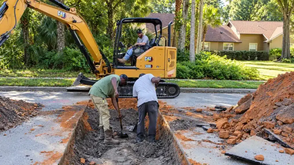
For older facilities facing drainfield decay, simply replacing pipe with identical materials rarely solves the underlying physics problem. Advanced diagnostics, including specialized sewer and drain services and soil core sampling, are necessary to evaluate soil stratigraphy, identify clay lenses, and establish true seasonal water table levels before redesigning the absorption array.
Advanced Hydraulic Remediation & Regulatory Standards in Central Florida
Overcoming high-water-table constraints requires engineered mound systems, aerobic treatment units, and strict adherence to Florida Environmental Protection and Department of Health standards.
When natural site topography and high groundwater levels prevent a standard below-grade drainfield installation, civil engineers must modify the site hydraulics. In Central Florida, the most common structural engineering solution is the construction of an elevated mound system.
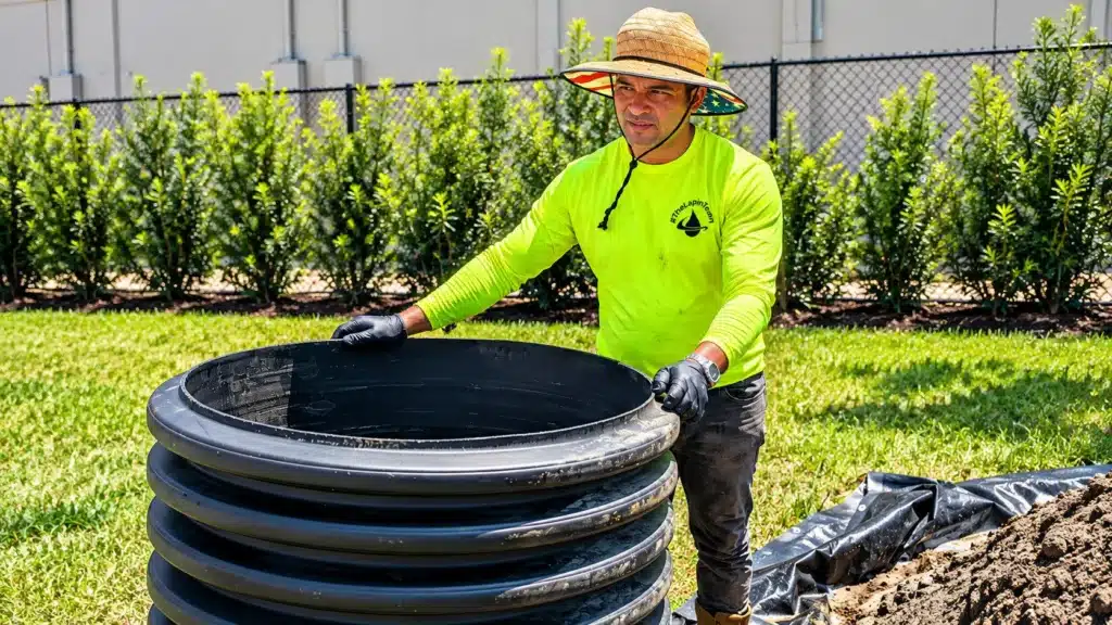
A mound system artificially raises the absorption surface above the native grade using clean, coarse silica sand. By building the absorption bed upward, engineers re-establish the mandatory 24-inch unsaturated vertical treatment zone above the true seasonal high-water table.
Cross-Sectional Layers of an Engineered Mound System
An elevated sand mound is constructed from top to bottom through the following specific engineering layers:
- Topsoil & Vegetative Cover: A protective layer of native turf grass and topsoil that prevents erosion, allows gas exchange, and sheds surface rainwater runoff.
- Pressure-Dosed Distribution Network: A network of small-diameter Schedule 40 PVC lateral pipes equipped with engineered discharge orifices to distribute effluent uniformly.
- Clean Sand Fill Matrix: A carefully graded, coarse silica sand layer providing a minimum of 24 inches of artificial unsaturated treatment depth.
- Native Ground Interface: The original soil surface, scarified prior to installation to ensure seamless hydraulic connection between mound sand and natural subsoil.
- Seasonal High Water Table Zone: The natural saturated groundwater boundary below, which remains isolated from untreated effluent.
However, elevated mounds introduce new mechanical and physical considerations that demand precise execution:
- Pressure Distribution Requirements: Elevated mounds cannot rely on simple gravity flow, as liquid would pool at the closest point of entry. Heavy-duty submersible pumps force effluent through small-diameter schedule 40 PVC lateral pipes drilled with precise discharge orifices, ensuring equal distribution across the entire bed.
- Slope and Seepage Control: Sand mound side slopes must be engineered with precise pitch ratios (typically 3:1 or 4:1) to prevent lateral effluent breakout along the sides of the mound during peak loading periods.
- Advanced Treatment Integration: Where land footprints are limited, Aerobic Treatment Units (ATUs) or Performance-Based Treatment Systems (PBTS) are installed prior to the drainfield. These systems inject oxygen directly into the treatment tank, dropping Biological Oxygen Demand ($BOD_5$) levels below $10\text{ mg/L}$ before liquid ever touches the soil. This eliminates the heavy biomat layer entirely, allowing for a reduced absorption footprint under Florida Department of Environmental Protectionguidelines.
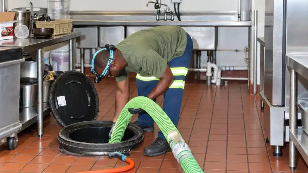
For commercial properties, restaurant operators, and industrial sites, high-water-table management is further complicated by municipal FOG (Fats, Oils, and Grease) regulations enforced across Orange and Seminole counties. Un-intercepted grease entering an elevated drainfield coats soil particles with hydrophobic hydrocarbons, causing immediate hydraulic failure regardless of water table depth.
Combining high-capacity, properly maintained grease interceptors with pressure-dosed absorption fields protects both commercial infrastructure and local aquifers.
Whether managing high-volume commercial lift station installations, civil underground utility connections, or residential septic repairs, engineering around high groundwater demands deep experience across multiple trade disciplines.
Lapin Services brings over six decades of dedicated Central Florida experience to complex site challenges. Holding triple-master licensure—as a Master Septic Contractor (SM0890812), Certified Plumbing Contractor (CFC1428594), and Underground Utility Contractor (CUC1223686)—our team delivers fully compliant, site-specific solutions designed to withstand Florida’s toughest environmental dynamics.
External References
- Florida Department of Health – Onsite Sewage Programs
- U.S. Environmental Protection Agency – SepticSmart Program
- Florida Department of Environmental Protection
Key Takeaways
- Unsaturated Separation is Essential: A minimum of 24 inches of unsaturated soil must be maintained between the bottom of a septic drainfield and the Seasonal High Water Table (SHWT) to ensure proper pathogen removal and fluid flow.
- Water Tables Destroy Biomat Equilibrium: Elevated groundwater deprives drainfield soil of oxygen, transforming beneficial aerobic treatment zones into anaerobic environments that produce impermeable biomat layers.
- Percolation Rates Require Context: Fast percolation rates in Central Florida sand can lead to premature failure if systems are not designed around the Long-Term Acceptance Rate (LTAR) and daily surge volumes.
- Mound Systems Re-establish Hydraulics: Elevated sand mounds artificially elevate the absorption area, utilizing pressure-dosed distribution to bypass native high-water-table constraints.
- Triple-Licensed Authority Matters: Resolving complex groundwater and wastewater challenges requires integrated plumbing, septic, and civil underground utility expertise.
Professional Site Remediation & Civil Utility Support
Managing high water tables, site percolation challenges, and complex municipal utility requirements demands field-tested engineering and execution. Whether you are dealing with an active drainfield failure, planning a commercial site development, or upgrading critical infrastructure, Lapin Services provides 24/7 technical support, diagnostic camera inspections, hydro-jetting, and complete utility installation.
Contact our team today to schedule an onsite diagnostic consultation or request a quote by visiting our Request a Project Quote Page or calling (407) 326-3367.